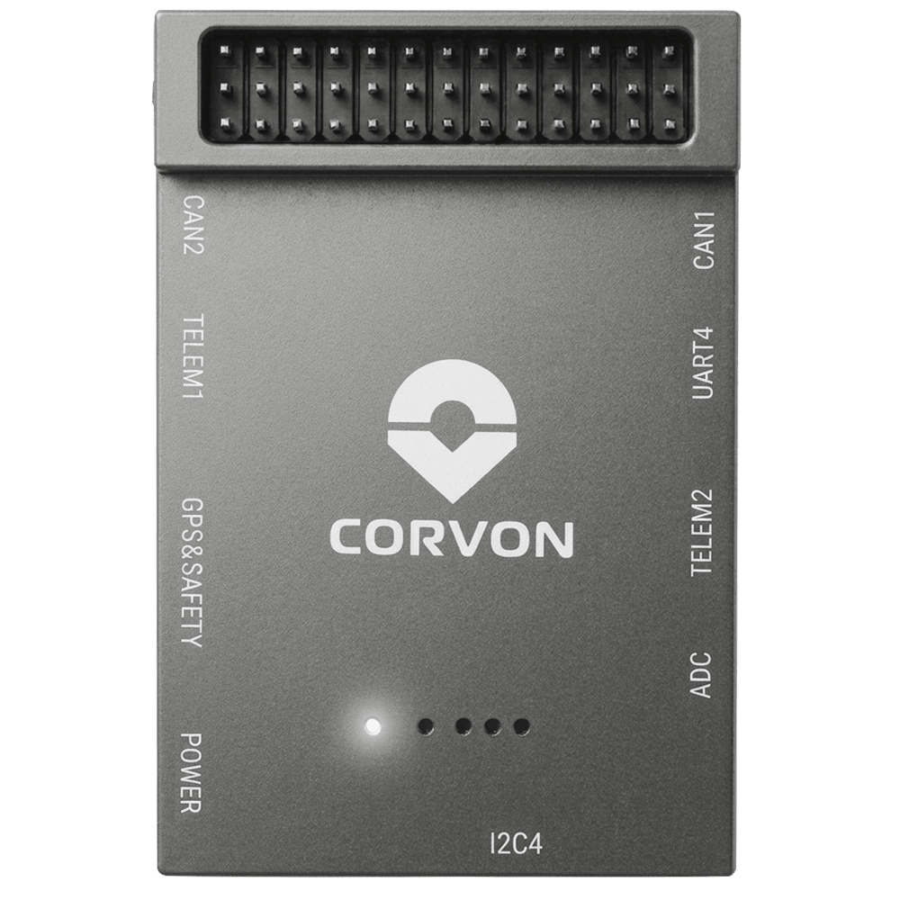
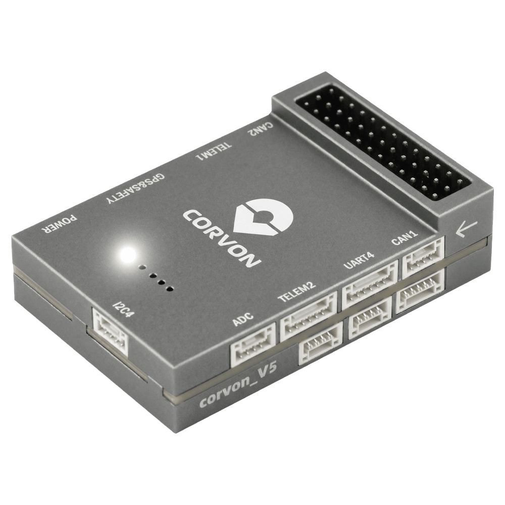
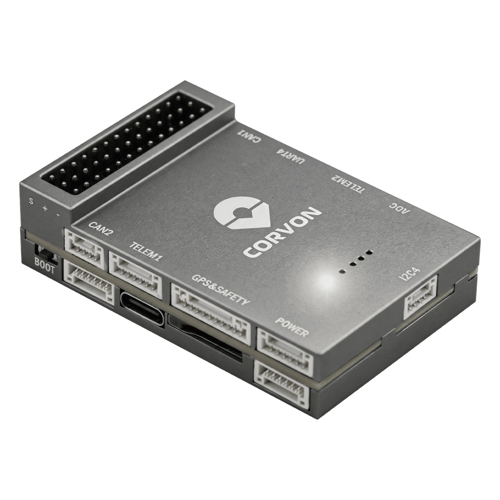
CORVON V5 Autopilot
PX4 v1.18WARNING
PX4 не розробляє цей (або будь-який інший) автопілот. Contact the manufacturer for hardware support or compliance issues.
The CORVON V5 is based on the Pixhawk FMUv5 design standard and runs PX4 on NuttX.
INFO
This flight controller is manufacturer supported.
Specifications
Main FMU Processor: STM32F765IIK
- 32 Bit Arm® Cortex®-M7, 216MHz, 2MB memory, 512KB RAM
On-board sensors:
- Акселератор/гіроскоп: ICM-20689
- Акселератор/гіроскоп: ICM-20602
- Акселератор/гіроскоп: BMI088
- Магнітометр: IST8310
- Барометр: MS5611
Interfaces:
- 8 PWM outputs
- 3 виділених PWM/Capture входи на FMU
- Виділений R/C вхід для CPPM
- Виділений вхід R/C для Spektrum / DSM і S.Bus
- Аналоговий / PWM вхід RSSI
- 4 загальних послідовних порти
- 3 I2C порти
- 4 шини SPI
- 2 CAN шини
- Аналогові входи для напруги / струму з батареї
- 2 додаткових аналогових входи
- Підтримка nARMED
Power System:
- Power Brick Input: 4.75~5.5V
- USB-C Power Input: 4.75~5.25V
Weight and Dimensions:
- Weight: 42.1g
- Dimensions: 61.2 x 40 x 15.9mm
Other Characteristics:
- Operating temperature: -20 ~ 85°C (Measured value)
Where to Buy
Connectors and Interfaces
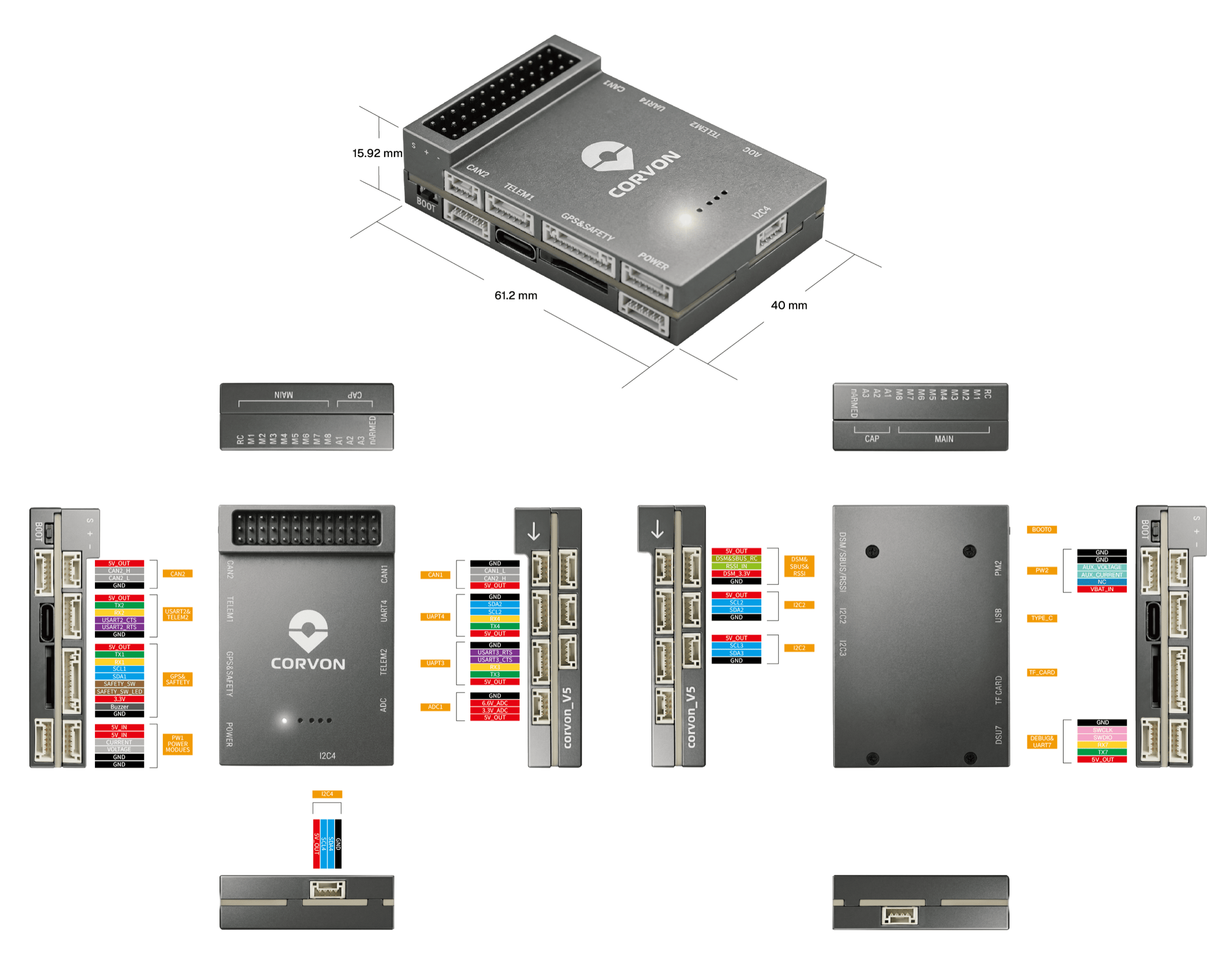
Схема розташування виводів
Download Corvon V5 pinouts from here: corvon_v5_pinout.xlsx
Налаштування послідовного порту
| UART | Пристрій | Порт | Flow Control |
|---|---|---|---|
| USART1 | /dev/ttyS0 | GPS | - |
| USART2 | /dev/ttyS1 | TELEM1 | Так |
| USART3 | /dev/ttyS2 | TELEM2 | Так |
| UART4 | /dev/ttyS3 | TELEM4 | - |
| USART6 | /dev/ttyS4 | RC | - |
| UART7 | /dev/ttyS5 | Debug Console | - |
| UART8 | /dev/ttyS6 | Reserved for optional onboard RTK module | - |
INFO
UART8 is reserved for an optional onboard UM982 module footprint and is not intended for general external use.
Radio Control
Для того щоб керувати транспортним засобом вручну, потрібна система радіоуправління (RC) (PX4 не потребує системи радіоуправління для автономних режимів польоту). Вам потрібно вибрати сумісний передавач/приймач і зв'язати їх таким чином, щоб вони взаємодіяли (ознайомтеся з інструкціями, що додаються до вашого конкретного передавача/приймача).
The ports and supported protocols are:
DSM/SBUS/RSSI(FMU): SBUS, DSM/DSMX, ST24, SUMD, CRSF, and GHST receiversRC: PPM
For PPM and S.Bus receivers, a single signal wire carries all channels. If your receiver outputs individual PWM signals (one wire per channel) it must be connected via a PPM encoder.
GPS & Compass
PX4 supports GPS modules connected to the GPS port(s) listed below. The module should be mounted on the frame as far away from other electronics as possible, with the direction marker pointing towards the front of the vehicle.
The GPS ports are:
GPS&SAFETY(FMU): 10-pin JST GH (Pixhawk Connector Standard) — GPS, compass (I2C), safety switch, buzzer, LED.
Вбудований безпечний вимикач в GPS-модулі увімкнений за замовчуванням (коли включений, PX4 не дозволить вам готувати до польоту). To disable the safety switch press and hold it for 1 second. You can press the safety switch again to enable safety and disarm the vehicle.
PWM Outputs
This flight controller supports up to 8 FMU PWM outputs (MAIN).
DShot is not supported.
The 8 outputs are in 3 groups:
- Outputs 1-4 in group1 (Timer1)
- Outputs 5-6 in group2 (Timer4)
- Outputs 7-8 in group3 (Timer12)
All outputs within the same group must use the same output protocol and rate.
Debug Port
The PX4 System Console and SWD interface operate on the FMU Debug port (DSU7).
The debug port (DSU7) has the following pinout:
| Pin | Сигнал | Вольтаж |
|---|---|---|
| 1 | GND | GND |
| 2 | FMU_SWCLK | +3.3V |
| 3 | FMU_SWDIO | +3.3V |
| 4 | DEBUG RX | +3.3V |
| 5 | DEBUG TX | +3.3V |
| 6 | 5V+ | +5V |
WARNING
The 5V+ pin (6) provides 5V, but the CPU logic runs at 3.3V!
Some JTAG/SWD adapters (like SEGGER J-Link) may use the Vref voltage pin to set the logic level on the SWD data lines. Connecting 5V to the adapter's Vtref can damage the CPU. For a direct connection to a Segger Jlink, we recommend you use a 3.3V source to provide Vtref to the JTAG adapter (i.e. providing 3.3V and NOT 5V).
Номінальна напруга
CORVON V5 must be powered from the POWER connector during flight, and may also be powered from USB for bench testing.
- POWER input: 4.75~5.5V
- USB input: 4.75~5.25V
The PM2 connector cannot power the flight controller. On PX4, do not use this interface.
Збірка прошивки
Щоб зібрати PX4 для цього контролера:
make corvon_v5_defaultВстановлення прошивки PX4
Прошивку можна встановити будь-якими звичайними способами:
Build and upload the source
shmake corvon_v5_default uploadLoad the firmware using QGroundControl. You can use either pre-built firmware or your own custom firmware.
INFO
If this target is not listed in QGroundControl, build and upload from source or load a custom firmware file (see Installing PX4 Main, Beta or Custom Firmware).
Підтримувані платформи / Конструкції
Будь-який мультикоптер / літак / наземна платформа / човен, який може керуватися звичайними RC сервоприводами або сервоприводами Futaba S-Bus. The complete set of supported configurations can be seen in the Airframes Reference.
Зображення